
Solving Industrial Monitoring Challenges through Wireless I/O
Remote monitoring and control applications present a range of challenges. In recent years, new technologies and products have emerged to address some of these challenges, but in many cases these products are limited and provide only partial solutions. The variety and complexity of applications has driven a need for an equal variety of features. End-users want feature-rich solutions that they can configure to meet their unique needs, with the configurability to apply them as needed. The need to accommodate legacy systems as well as new installations has underlined the necessity of compatibility and configuration. End-users want products that incorporate as many useful features as possible to keep capital and maintenance costs at a minimum. “The devil is in the details” and upcoming monitoring solutions must address those details comprehensively.
We are surrounded by applications that call for creative communication and monitoring solutions. Increasingly, end users are searching for comprehensive solutions to applications. Whether adding remote I/O to a legacy PLC, extending analog and digital monitoring to a remote plant, or connecting serial devices without creating new hardwired links, industrial users want solutions that are simple to implement, reliable and cost-effective.
Applications for wireless remote I/O solutions abound. Consider a few of the following examples:
- Water and wastewater treatment utilities are looking for affordable and reliable ways to monitor the status of remote pumps, storage tank levels, chemical additions rates, and metering systems. They need the ability to capture discrete (digital) status information and analog measurements, and send them back to a central control system /human machine interface (HMI). Often discrete and analog control signals must travel in the opposite direction. Communications links must be simple to install, reliable under all conditions, failsafe, and secure.
- The oil and gas industry needs systems that can communicate wirelessly with remote wellheads and tank farms. Again, discrete and analog signals must travel in both directions. The communications system must interface to existing systems using standard serial interfaces. The equipment must comply with industry standards and provide failsafe features.
- Expanding process plants need simple and cost-effective solutions to expand PLC I/O into new process areas. The equipment often must be compatible with legacy equipment and protocols such as Modbus.
This whitepaper considers the types of features and capabilities that are needed in the next generation of wireless I/O products and provides suggestions for what is important in terms of equipment, installation and support.
Why Wireless?
Whether you are adding to existing systems and equipment or creating new infrastructure, distance and barriers can be your enemy. Remote monitoring and control can be a costly proposition at the best of times, but the cost of hardwired connections can make an application non-viable. In some cases hard-wiring is simply not possible. Adding I/O within an existing plant may not involve long distances, but the cost and difficulties associated with adding conduit and wiring to an existing plant may be far greater than the added cost of utilizing a wireless link. Distributed systems located in rural areas present additional challenges. Trenching in new communications lines may not be cost effective, and existing communications links (e.g., telephone, cellular) may not be reliable or even available. Hardwired connections are simply not feasible when geographical barriers such as mountains and rivers are involved, or when man-made structures such as highways and buildings block wiring routes.
RF Considerations: It’s more than just Radiated Power
Of course, wireless systems present their own challenges. Many factors can enhance or inhibit the effective range of any RF communications system. Often, users assume “the more power, the longer the range.” The truth is a bit more complex.
Transmitter power IS important, but it is also important to understand that the amount of energy that an RF device can radiate into the air is regulated by government agencies, so the impact of transmitter power on range is limited by how powerful a transmitter can be used. Different frequency bands are allowed different maximum transmitter power levels. For example, a wireless device operating in the 2.4 GHz range is typically allowed a much lower power level than one operating in the 900 MHz range.
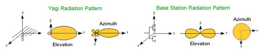
Antenna gain is also a factor in the amount of radiated energy. Antenna gain refers to the ability of an antenna to focus the RF into a narrower, more useful, plane. This effectively increases the signal strength. Antenna gain is expressed in decibels (db). An antenna with higher gain will be able to use weaker signals more efficiently than an antenna with lower gain. When referring to antennas, gain is always directional gain. An antenna does not add energy to a signal; rather it directs radiated energy in some directions at the expense of other directions. Since this occurs in three dimensions, antenna radiation pattern graphs are very useful. Typical radiation patterns are depicted in the figures below.
Receiver sensitivity is not regulated and thus presents a variable from which considerable competitive advantages can be lost or gained. Receiver sensitivity is the measure of the minimum power level at which the receiver is able to detect the RF signal and demodulate the data. Sensitivity is measured in dBm, which is usually a negative value. So, -110 dBm is better for longer ranges than -93 dBm. Poor receive sensitivity reduces range.
Antenna cable considerations go hand in hand with the antenna gain. Using a low loss cable maintains the signal level, which can be especially important if the distance between the antenna and transmitter/receiver is long.
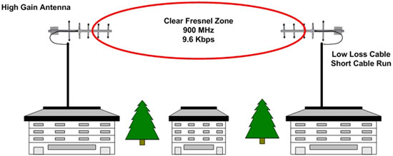
Fresnel zone is the path between the transmitter and receiver. When unobstructed, radio waves travel in a straight line. However, when there are obstacles in the way, radio waves reflect off them. This can cause multiple signals to arrive at the receiver at different times (called multipathing). The received signal loses energy, and it becomes more difficult to retrieve the information the radio signal carries. An unobstructed line-of-sight path between transmitter and receiver is the ideal solution.
Radio frequency interference (RFI) is electromagnetic signals from other emitters, either intentional or unintentional, that can degrade and interfere with successful reception of the desired signal. Sources for interference can be other radio systems such as cell phones, public service transmitters, and commercial broadcast stations. There is almost always some RFI present but its ability to reduce range depends on its proximity to the receiver. In some cases nothing can be done about RFI, other than locate the wireless link away from the interference (if that is possible).
Over-the-Air Data Rate is a factor that can also determine range. As the data rate of a system increases electrical noise has a greater interference effect on the received signal. The farther the signal travels, the more the signal is degraded, decreasing the system’s ability to effectively communicate. Doubling the data rate can reduce range by up to 30%. Reducing the data rate improves range.
Frequency. The general rule of thumb is that the higher the frequency the shorter the range. Several factors affect this. Higher frequency signals do not bend around the curvature of the earth, limiting range to line of sight. Higher frequency signals are also more easily absorbed by trees, shrubs and other foliage, particularly when they are wet.
Wireless Options
Each wireless solution has its uses and champions. Finding which of these makes sense in a given industrial setting starts with the best match of distance, data rates, number of devices, cost, power required, and especially reliability. Here are some of the more popular options:
Bluetooth is useful for short distance links (to 100 meters) when incorporating small number of devices (up to 8). Often defined as “personal networks,” these have real but limited industrial applications.
WiFi (802.11) is the standard for fixed shorter distance (to 160 meters) commercial applications. It receives much development support because of bandwidth (to 1 gigabits per second). Even so, for industrial applications it has more bandwidth than typically needed and only limited range. It also uses the most computing resources and electrical power and has the largest physical footprint. Industrial WiFi installations should always have added security measures, as most laptops are otherwise potential access points.
Zigbee is a more recent entrant to the field and is a proprietary technology. It has low power needs (batteries may last for years) and forms a mesh network with multiple data channels to extend range. Devices take the least space, and up to 64,000 nodes can be connected. Drawbacks include relatively short distances reached by a single link (as low as 20 meters), low bandwidth (720 kilobits per second) and limited interoperability with other systems. Most important in industrial settings – as a new technology it is not supported by a long history of reliable applications.
Cellular devices for industrial applications can reach anywhere that has adequate cellular service. These may make sense over long distances where multiple cellular service towers are within range. However, cell service is not always available or guaranteed, and the potential conflicts with metal structures and need to pay for cellular service for each node may be limiting factors.
Proprietary RF systems increasingly are considered the best solution for industrial wireless communications. Proprietary RF systems provide a combination of reliability, capability, industrial features and longer distance links (up to 40 miles with high gain antennas). Proprietary systems also provide higher levels of security than many other systems. Because proprietary systems are designed for a narrower range of applications, compromising them would require the use of identical core technology, compression, packet and frequency transmission patterns.
Proprietary wireless systems typically use frequencies in the lower ranges that provide good coverage and penetration. Some manufacturers use the non-licensed ISM bands (900 MHz and 2.4 GHz).
One possible drawback to using proprietary systems is getting “locked in” to a single manufacturer. Finding a stable company that has great technical support, is competitive on price and performance and satisfies customers in a wide range of industries avoids potential problems.
Wireless Decisions
Based on the wireless considerations and options already discussed, when choosing a wireless solution several questions must be asked, and answered, to ensure a wireless link will perform satisfactorily.
Is line-of-sight propagation possible? If not, can attenuation and multi-pathing be overcome to ensure reliable communication? Are the ideal, or at least acceptable, antenna and equipment mounting locations accessible and available? What frequency range best suits the application? Does the supplier of the equipment provide enough information, tools and support to assist with getting these answers? Does their product line include all the products and options to ensure success?
Based on the assumption that you are trying to create an industrial wireless link, and need the distance, reliability and configurability that entails, you are probably looking at using a proprietary RF system. For the purposes of this discussion we will start there.
Before selecting any specific equipment it is important to do some analysis on the communication environment—to perform a site assessment. A site assessment is an analysis of the distance, terrain, obstacles, foliage, potential RFI sources and other factors that may affect the operation of the communications system. Depending on the challenges inherent in your application you may be able to do your own site assessment. In more complex or critical applications it may be advisable to have one done by a consultant. Ideally, if you have a clear line-of-sight between the transmitting and receiving antennas, you can have reasonable confidence that a wireless link will operate successfully given adequate power in the appropriate frequency range. Still, you should consider whether the environmental conditions could change seasonally, or because of other changes in the area. You should also investigate whether there may be sources of RFI nearby.
You should also do a link budget analysis. A link budget analysis considers the transmitter power, sensitivity of the receiver, antenna gain, antenna cable losses, receiver sensitivity and other factors to determine whether a system can reliably communicate. The calculations are beyond the scope of this article, but it may be comforting to know that some wireless equipment suppliers provide online wireless range calculators and other technical support that will ensure success in this area.
Once you have determined distances, power requirements, antenna configurations and other factors needed, you can select the best operating frequency based on the needs of your application. For example, 900 MHz systems typically send at higher power levels and reach farther distances than 2.4 MHz, which transmit at lower levels. One typical 900 MHz radio modem has a 3000 foot range indoors (under optimal conditions). A similar 2.4 GHz radio modem has a 300 foot range indoors. Of course, these examples refer to ideal conditions when using the supplied antenna. When operating indoors there may be obstructions, RFI and other factors that compromise the range. Outdoors, these same modems may have ranges of up to 14 miles (900 MHz) and 1 mile (2.4 GHz). Exchanging the supplied antenna for a high gain antenna can extend the ranges up to 40 miles and 10 miles respectively.
Obviously, antenna choice can be important. Antenna choices include several different sizes and configurations of omni directional and yagi configurations, in both 900 MHz and 2.4 GHz models. As the name suggests, omni directional antennas transmit and receive in a circular pattern. Yagis are directional antennas, focusing energy mostly in one direction when transmitting, and providing enhanced sensitivity in one direction when receiving. Antenna gain can range from 3 dB to 8 dB for omni directional antennas and 6 dB to 12 dB for yagis.
Based on the type and power range of the transmitter selected, and the link budget analysis, you can select the necessary receiver sensitivity. Quality wireless receivers provide receiver sensitivities in the neighborhood of -114 dB.
Remote I/O Basics
The primary reason for employing wireless remote I/O in industrial systems is to capture status (discrete) and measurement/control (analog) information at one location and transfer it to another location. Ideally, the link should be able to carry information in both directions, enabling it to be used for both monitoring and control. For example, a system monitoring a remote irrigation pumping system may carry the status of the pump (on/off), a flow rate measurement signal (pulse frequency) and a pumphouse temperature measurement signal (analog voltage or current signal) to a SCADA system in the control room of a central monitoring station. Control signals to start and stop the pump, and possibly an analog signal to send to a variable frequency drive (VFD) that controls the speed of the pump, may be sent in the opposite direction, from the control station to the pumphouse.
I/O devices must be able to accommodate a variety of different standard discrete and analog signals. The I/O device must be able to accept inputs from field equipment with NPN or PNP discrete outputs, contact closures and voltage levels. High state voltage levels may range from as low as 1 VDC to 48 VDC. In some cases, field equipment incorporates pulse/frequency outputs—variable frequency pulse trains in which the pulse rate represents an analog value (e.g., the speed of a motor or some other parameter). The I/O device must accept analog inputs in voltage or current format in several ranges (0-10V, 0-5V, 0-20mA, and 4-20mA). The I/O device must be able to provide similar outputs, including the ability to sink or source adequate levels of current (30 to 40 mA).
Remote I/O Applications
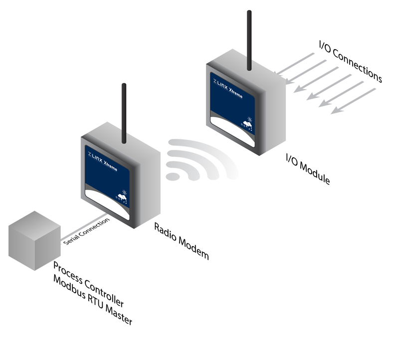
One application of wireless I/O is simple wire-replacement. Inputs and outputs at one location need to be carried wirelessly from one location and recreated at another location. Remote I/O can provide a solution in a peer-to-peer mode of operation. Status points and analog signals connected to the inputs one wireless I/O device are transmitted across the link and recreated on the outputs of a similar I/O device at the other end of the link. Simple applications such as this can often be “plug and play”, requiring little to no configuration by the user.
By adding modules configured as repeaters, the range of a link can be extended. However, latency must be considered when repeating data through multiple nodes. Each node contributes a few milliseconds to the overall signal delay to the overall communication delays, which may become critical in some applications.
Modbus and Remote I/O
Although some new installations are built using single supplier (and sometimes proprietary) monitoring and control systems, in many cases wireless I/O systems are being interfaced to existing systems. Often these systems are a mixture of legacy and more up-to-date equipment from a variety of sources. Many of these communicate using Modbus. Modbus is a proven and reliable industrial communications protocol first introduced more than 25 years ago for communicating between PLCs and remote terminal units. Modbus transfers status (discrete) and register (digital representations of analog values) information from an I/O device to a memory location in a PLC or other device, and from the PLC/other device to the I/O device.
Modbus provides a number of advantages for wireless I/O. It is a relatively simple, open, and free protocol, and it is ubiquitous—many existing systems already use or support it. Most importantly, Modbus is well understood by many industry personnel, and can be applied with minimal additional training. PLCs and other devices often use Modbus to communicate with other devices over R-232 or RS-422/485 serial links. With more than seven million Modbus nodes in North America, the ability for remote I/O systems to communicate using the Modbus protocol is a valuable feature. The capability and reach of legacy PLCs can often be expanded by simply writing ladder logic to address remote I/O, communicating with it via a serial link to a wireless modem and from there to the remote I/O via the wireless link.
Modbus’ main disadvantage is that it is a master/slave protocol. As such, slaves only respond when they are polled. The slave then responds with the status or register value requested. In some applications “exception reporting” may be a desirable feature. Exception reporting (available on some manufacturers’ remote I/O systems) initiates a special message from the Modbus slave to the master when a status input detects a pre-configured status, or if an analog input reaches a low or high limit (as pre-configured). This enables the supervisory system to respond immediately, or as necessary, to the exception.
 Configurability
As the size and capability of a system increases, so does its complexity. Sometimes a simple purpose-built solution can be the easiest to implement and use, but more often a feature-rich solution that is easily configurable to your application is better. Look for wireless I/O systems that provide the configuration options you need, a simple and clear configuration interface, clear user documentation and strong technical support. Increasingly, products are available with “plug and play” capabilities. In some cases by simply pressing a button the device can be programmed for basic point-to-point operation. In-depth configuration is accomplished from a computer via a built-in USB interface. Look for products that provide simple to use software for configuration.
Fail-safe Features
Wireless I/O can be a valuable part of a monitoring and control system when everything is working perfectly, but what about when things go wrong? For example, what happens if the wireless link is interrupted by an electrical storm, remote power loss or other failure? How do inputs and outputs react to a loss of communication? It is important to look for systems that provide configurable fail-safe conditions. A well designed system should allow discrete outputs to be configured to a known state when communications is lost. Similarly, you should be able to configure analog outputs to assume a specified value. Some devices also provide a dedicated output to drive an alarm in the event of communications link loss.
Security
In recent years, the security of many industrial installations has become a significant issue. Obviously, wireless communications links have an intrinsic vulnerability to security risks unless steps are taken to mitigate them. Look for wireless systems that provide trusted and accepted security features and provisions. Wireless links should provide AES security with 128 or 256 bit encryption. AES encryption is the standard adopted by the US government to secure data being transmitted over-the-air.
Setup and Testing
Before actually installing a wireless I/O system it is wise to bench test all the equipment. The benefits of configuring and testing a system under controlled conditions are well worth the investment of time. Sometimes factors may reveal themselves that you had not anticipated. During bench testing these glitches can be rectified simply and easily. Of course, you will still have to test the system in the field to ensure it was installed correctly, and that your site assessment was accurate.
Expansion Options
Sometimes a remote I/O application can grow beyond its original design specs. More I/O points may be needed. If this situation may be possible in your application look for product families that allow you to add modular I/O.
Mounting Options
Remote I/O products are available in a variety of mounting options. If the equipment is to be mounted inside an existing enclosure you may need DIN rail mountable models. Some applications require the equipment to be housed in an enclosure that can withstand dust, hot and cold weather conditions, wash downs, and even abuse. IP67 is an example of a standard enclosure specification that can withstand the dust and water that is prevalent in outdoor and industrial plant environments.
Reliability and Dependability
It almost goes without saying that industrial equipment used in remote—often extreme—environments must be reliable and dependable. This is also true for the systems used to remotely monitor industrial equipment. Wireless I/O equipment that is installed outdoors or in industrial environments should be capable of withstanding a wide range of temperatures (e.g. -40 to 74ºC), humidity, vibration, power supply fluctuations and physical abuse. Specifications for the equipment, as well as the standards, are important considerations.
Conclusion
Building or expanding industrial control systems to provide remote monitoring capabilities can be a challenge. By choosing the right equipment, you can save a lot of time and effort, now and in the future. The equipment you choose should be feature-rich, configurable, scalable, and employ popular communication protocols. It should be chosen and applied with the realities of RF communications in mind. It should have features such as the ability to send timely notifications, detect communication failures, and automatically implement fail-safe functionality. It should make use of industry standards for secure data transmission. It should be dependable and designed for outdoor use and industrial environments. It should come with a clear configuration interface, good documentation, and strong technical support. The “devil is in the details” but the solution is in careful planning, and selection of the best equipment for the application.
Recommended Posts
3 Questions to Ask Before Selecting an LTE WAN
June 15, 2018
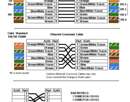
Ethernet Cables: RJ45 Colors and Crossover
May 21, 2018