
Ten Commandments of Fiber Optics
1. Thou shalt not connect SM (Single Mode) fiber products over MM (Multi Mode) fiber cables, nor MM products over SM fiber cables.
Fiber is not a one size fits all. So many folks try to use what they have inherited and make it all work. Fiber is defined by what types of wavelengths it can accommodate and what types of lasers are used based on its core’s capabilities. SM fiber can cover up to 130Km in distance due to the strong lasers that shoot the light that far, through a core size of 9/125 micron. MM fiber, on the other hand, is ideal for short distance applications, up to 2Km, through a core size of 62.5 micron (50 micron still used in some installations). The MM core size is larger and lends itself to modal dispersion (lots of light bouncing around inside the core). If you install SM products over a MM fiber run, the end result are CRC errors due to packets dropping; this will not make thy network users happy.
2. Thou shalt not fear attenuation when deploying SM fiber if it is too hot (ouch!!)
“You may need attenuation.” Ah, that dreaded piece of advice. What is it, how do I avoid it? Attenuation is a condition relevant to SM fiber, due to the long distances SM fiber can cover. Sometimes SM fiber is installed over a short distance (yeah, I know, the installer should have installed MM fiber instead). Under this condition, a SM fiber laser can be described as “hot”—no it hasn’t been baking in the oven, it has a strong signal strength to shoot over a given distance it is capable of achieving. So what does attenuation provide? Simply put, it is a way of reducing the signal strength without impacting the integrity of the line or throughput of data. Attenuators are available in the form factors of an O ring (slips onto the ST connector type interface), a coupler on the fiber line itself, or as a connector cap to clip onto a fiber interface connector. They are available in various values of dB, and adding 10dB is often the “wet thumb” approach if you don’t want to spend time performing heavy mathematical calculations. Multi Mode fiber is not susceptible to the need for attenuation, as there is too much modal dispersion going on in the first place.
Air gap attenuation: if thy customer does not believe he needs attenuation, ask him to back off the connector on the transmit port of the fiber, while maintaining a link and continuing to send data. This is referred to as “air gap attenuation”. If the data starts flowing through with loss, attenuation does need to be added.
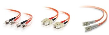
3. Thou shalt know thy connector types
Connectors for fiber transceivers are SC, ST, and LC. SC, stick and click, is a square type connector. ST, stick and twist, is a bayonet type, round connector. LC—sorry, no catchy description. It was developed by Lucent in the early 2000 era to address field techs complaining that ST and SC were too bulky and easy to dislodge from the fiber interfaces on equipment. Rolling forward to 2009, SFPs were introduced with the connector type of…drum roll…. LC. LC looks like a compact SC connector. There are other connector types, such as MT-RJ and VF.
4. Thou shalt not buy two of the same product for Single Strand Fiber
Single Strand Fiber (SSF) for SM has the unique ability to use one strand of fiber by using two independent wavelengths, often 1310 and 1550nm. SSF must be used in specific pairs, that is, one is a 1310/1550 device (transmitting at 1310, receiving at 1550) and the other must be a 1550/1310 (transmitting at 1550, receiving at 1310) device. 1550nm is more expensive than 1310nm, due to the type of laser and what kind of distance it can cover. Combine that with the cost of SSF technology and the price is going to be more expensive than dual strand of either wavelength. Naturally, admins look to save money, and the inclination is to buy two of the 1310/1550 device. What you end up with is two left shoes. SSF is like buying a pair of shoes; you need a left shoe and a right shoe. Or is that a left sandal and a right sandal?
So what is the benefit of SSF? Well, if you are between the proverbial rock and a hard place due to one strand of fiber available in a bundle, it is certainly going to be cheaper to purchase SSF products than digging up the run to add another bundle of fiber. On the bright side, if the lines of SM fiber are being used up quickly due to growth, this is the time to double the fiber capacity by using SSF products.
5. Too many connectors and splices can lead to a very degraded line
We all know copper has its set of issues: distance limitations, degradation of copper, easy to hack. Fiber has some challenges too. Fiber’s performance is impacted by connectors, splices and attenuation per Km, based on the type of fiber. SM fiber will not suffer as much signal loss per Km as MM will. Even though each value is small, nevertheless it impacts the line. Loss factors should be calculated when deploying products over a fiber run. Loss factors are based on typical values: 0.75db per connector, attenuation per km (.22Km for SM and .35Km for MM), .01db per splice and a 3dB margin for safety. The more splices and connectors you have in a segment, the greater the loss on the line, which translates to a degraded line. If the line is too degraded, there is a possibility of over-coming this bad situation:
- Install a stronger-powered fiber optic device to compensate for the loss
- Consider decreasing the distance, to restore full data transfer on the line.
- Reduce the speed from say gigabit to Fast Ethernet. A faster speed shortens the distance that can be covered.
- You may have to have a new bundle of fiber pulled for the run (expensive, time-consuming).
6. Know thy Fiber Power Budget formula intimately.
When contemplating the kind of fiber-based product to purchase, the power budget should be calculated for the project. The golden rule is “Transmit-Receive Sensitivity=Power Budget”. Some of this information is documented on the vendor’s spec sheet, so it is not mysterious, hard- to- find information. The output power and receive sensitivity values are listed as well as bias current and a whole lot of other stuff that is more than thou needs to understand. Calculating the budget is a good step, but the ultimate step is using a power meter to measure a given line of fiber.
7. Honor thy Laser Classifications, so as not to lose an eye..
There are different classifications of lasers for fiber. Ethernet, serial, DS3 and other types of fiber-based media converters typically use Class I, eye-safe lasers. This means no damage will occur on any of the equipment, but it is still not a good idea to view the port of a laser transmitter and possibly damage thine eye. Higher classifications of lasers in the order of value are used in Fiber Channel, medical , and weapons arena. Vendors should list such information in their documentation, or you will need to contact them.
8. Know thy Fiber transceiver connection (ferule) types
Optic laser connectors fall into two categories: Angle Polished Connectors (APC) and Ultra Polished Connectors (UPC). Typically, when we hear the words fiber connectors, we think in terms of ST, SC or LC. However, this verbiage also applies to the ferrule within the connector , at the end of the terminated fiber. The major physical difference between the two is the end-face geometry; the APC ferrule end-face is polished at an 8° angle, while the UPC is polished at a 0° angle. The APC 8° becomes significant when considering return loss issues. We won’t cover the technical aspects of the losses, but identify the connector types and to what industries they are applicable.
UPC connectors have been historically implemented on Ethernet network equipment, such as media converters, serial devices and fiber-based switches. APC connectors are usually implemented for FTTX and PON, the “triple play” to multiple customers, and ISPs increasingly use APC.
The common customer question: “is it possible to connect UPC to APC?” (no).
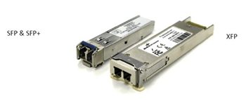
9. Thou Shalt understand the difference between an SFP, SFP+ and XFP before purchasing one.
Small Form Pluggable transceivers have different capabilities and/or form factor size. SFPs gave the fiber installations total flexibility, in that a cage could hold any fiber type/appropriate speed. Fixed fiber transceivers are still cheaper, but SFPs are decreasing in cost all the time. Generally, SFPs support speeds for 1 gig or 100Mbps, although one can find a (rare)T1 SFP. 10G transceivers are available in SFP+ and XFP. One cannot install a 10G SFP+ int
10. Honor the speed and protocols that fiber supports
Most fiber-based devices are defined by speed and protocol, relative to the product’s design and capability. If a gigabit network switch has a fiber interface on it, and it is labeled a GBIC, it must be connected to an Ethernet device capable of gigabit speed on its fiber interface as well. Protocol plays a part too: if an Ethernet gigabit network device is connected to a GPON device, even though they are both gigabit, they live under different protocols and cannot be connected to each other directly and effectively communicate.
There are mode converters, which convert one type of fiber to another, or the same type to another to extend distance. Mode converters are not confined to a protocol, but they must be defined by a speed range. A mode converter supporting up to 155Mbps cannot be connected to a gigabit mode converter, for example. However, there are devices such as WDM (two channel fiber, passive optics), that can be connected over any speed up to 10G. Understanding how to connect fiber to maximize its flexibility is the key to success.
Recommended Posts

Co-Creation, Paving the Way to a More Connected Future
November 27, 2018

The Benefits of a ‘Do It For Me’ Mentality in the IIoT
October 5, 2018

Why You Need to ‘Mind the Gap’ in Manufacturing Technology
August 31, 2018