
SimpleWire Replacement with Zlinx® Radio Modems: Knowledge, Tips, Fixes
A problem free wireless network installation is more than a wish, it’s what most of our customers experience.
But a little knowledge and planning up front makes succeeding on your first try more likely. We’ve gone to great lengths to make it simple enough to take your wireless modems out of the box, plug in power and data lines, and voilà, your network is wireless.
There are few things more satisfying than seeing data roll in just like you’d run miles of cable, but quicker, easier, cheaper – and still reliable. But it’s still possible you’ll run into interference. So here’s a short list of things to make your “out of the box” experience a good one.
ENVIRONMENT
The first thing to check is the environment you want to install your radio modems in. Is it outdoors or indoors? Will you send data “line-of-sight” or are there obstructions? What distance do you need to go? Are there wireless antennas on the same band nearby?
Once these are established, getting the right equipment is simple. None of these factors are barriers to a successful system. But they’ll determine best placement for your radio modems, your antennas and whether you’ll need one or more repeaters.
LATENCY
The majority of industrial applications function completely well with wireless instead of hard wired links. But with the convenience and flexibility of wireless comes some tradeoffs.
Latency, or delay between sending and receiving data, is greater with wireless. Most networks handle a little added latency just fine. We’ve never seen a situation that wasn’t solved by fine tuning response times.
For example, a Modbus network may poll PLCs every 10ms, or have devices set to receive a response within 10ms. Even if it’s just sending 200 bytes on a 115,200 baud connection, you’re still not going to get it in 10ms on a wireless network. A simple change in polling rates and timeout timers handles this with no impact to operations.
DISTANCE AND MODEM SELECTION
One of our claims-to-fame is our wide variety of radio modems. Long range, short range, 868 and 900 MHz, and 2.4 GHz. 1mW to 1W outputs. 900 MHz works mostly in North and South America, 868 MHz in Europe because of different allocation of the radio spectrum. 2.4 MHz works almost everywhere.
Now you’d think with this wide variety to choose from, you just couldn’t go wrong, right? It turns out there are still a few technicians out there, who manage to get it wrong by not understanding the need for a wireless “performance buffer.”
Way back in wireless pre-history, someone told an engineer, “Tell me the furthest mountain tops these things will transmit between.” So he did some calculations, and the next thing he knew it was on every printed page and web page: “Maximum range of this fine equipment is 40 miles.”
The real functional maximum range of any piece of wireless equipment, compared to the “Maximum Range” often advertised, is half that distance. An industrial wireless installation needs a 10:1 signal strength “performance buffer,” or a full 10 dBm signal strength buffer. Cutting the maximum possible distance in half makes up for most of that needed buffer.
Do you really need 10X more power transmitted than a bare minimum, just as a buffer? Well, yes. When materials, machines, money and people are at stake, it’s the safe, secure and sure thing to do.
So when our technical specifications state the maximum range with a directional antenna is 20 miles, you can count on your equipment to be capable of that range. But keep in mind there are still many factors that kind of performance depends on.
Other things being equal, it’s better to go with 900 MHz modems instead of 2.4 GHz ones. The physics of RF make it so the 900 MHz frequency goes further, penetrates non-metal walls better, and has greater receive sensitivity. It’s also less crowded with interference.
But if you’ve got a really loaded 900 MHz wireless network nearby, you might want to choose the 2.4 GHz instead.
SETTING UP THE EQUIPMENT
When your new modems arrive, there’s a natural inclination to just get them working and see what they’ll do. But if the first thing you do is send them out as far as they need to be, plug them in and turn them on, and nothing happens, it’s hard to tell what to fix.
It’s best to first conduct a round of bench testing. Either a loop back test or with equipment connected is fine. But if they don’t work there, neither will they in the field.
Other setup issues can range from non-matching channel numbers to 485 biasing termination. Our Quick Start Guides and manuals cover lots of ground, but if these aren’t enough help, please call.
ANTENNAS
Antennas aren’t difficult, but they can cause a lot of problems if you don’t understand some basics. If the signal doesn’t get through to the other end, your “wire” is, after all, effectively cut.
If there’s a single best fix for antenna problems, it’s to put the antenna higher. Sometimes it may be the only option, like to clear large grove of trees. But naturally there are limits, like neighbors and airplanes. And just a few added meters of height can make a big difference, if you’re competing with a nearby antenna on the same frequency.
There are two basic kinds of antenna typically used for radio modems. An omni-irectional antenna, usually a dipole or “stick” antenna, has shorter range but broadcasts 360°. “Omni” doesn’t mean “all” in this case, as these don’t broadcast or receive straight out from the tip.
The directional or high gain antenna is most often a Yagi multi-element. These have three or four (or more) dipoles lined up parallel, getting progressively shorter toward the front. They direct the signal so it works in one direction, for both transmitting and receiving.
For example, in a typical Modbus system the Modbus master uses an omnidirectional or dipole antenna that communicates with many devices. The slave devices, on the other hand, would most often be directional or Yagi antennas, as they only need to reach the master.
Polarization refers to the horizontal vs. vertical orientation of the antenna, which is also the orientation of the radio signal that’s sent or received. Both antennas must have identical polarization.
This leads to some interesting tricks with wireless setups. Four radio modems can share the same pathway, with two radios oriented horizontally and the other two vertically. This applies to directional yagis as well as omnidirectional dipoles.
Aiming a directional antenna is easy if you can see the other antenna. But if it’s too far to see, using a map or GPS and compass to point a more precise direction may be necessary to even start the process.
An RF site survey can be done up front to establish signal strength patterns in challenging settings. Changing modem placement can make a big difference in signal strength around high-power metal equipment. Some devices even have signal strength meters to help with this.
CABLES
Shorter is better. Fewer connections are better. And the longer the distance between your modem and antenna, the more you need cable that loses the least amount of signal strength possible along the way.
Of course, antenna grade cable is more expensive than regular coax, but it’s well worth it.
BAUD RATE AND RECEIVE SENSITIVITY
Baud rate or data rate is another tradeoff. Many core industrial applications don’t take much bandwidth, so this doesn’t have to be a problem.
However, baud rate can be an even more important as it affects the distance your wireless signal travels. As baud rate goes down, receive sensitivity goes up. And receive sensitivity has every bit as much to do with how far a wireless signal can be received as does transmit power.
Zlinx LR or long range modems are adjustable between 115,200 bps and 9,600 bps, to maximize performance in longer distance situations.
If the network is big enough over the air data rate can also be an issue. If this is the case, such measures as fine tuning polling frequency and similar are also effective here.
A WIRELESS DISASTER AND ULTIMATE SOLUTIONS
When all else fails, bring your modems back to your shop, reset all settings and options back to default and do a bench test. A little parable shows how understanding some basics can help after that.
A customer called in with no signal between his two modems. After a bench test showed the modems were OK, we reviewed one issue at a time. Come to find out, his dipole antennas were pointed antenna tip to antenna tip. No amount of signal strength could overcome that.
The cable between his base station modem and the antenna was an incredible length. With 15 different connectors and all kinds of different cable linked together, most of it wasn’t antenna cable, either. Once again, no wonder there was no signal.
SUPPORT
There are answers all your wireless questions. From product specs, network design and product selection, to ordering and system setup. Your best resource – and safety net – is our customer service, technical support and applications engineers.
Recommended Posts
3 Questions to Ask Before Selecting an LTE WAN
June 15, 2018
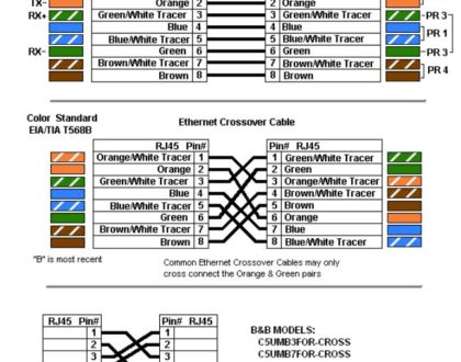
Ethernet Cables: RJ45 Colors and Crossover
May 21, 2018