
Fiber Optics in Networks
HOW OUTPUT POWER, ATTENUATION, DBM IMPACT A FIBER INSTALLATION FOR NETWORKS
Background on Fiber Optics
 Fiber optics is commonly used to connect network equipment between endpoints. Unlike copper, which covers no more than 100m, fiber can support up to 130Km of distance between endpoints. Some of the attributes of fiber are: immunity from EMI, security (hack-proof, unlike copper) for transmission of data, wide bandwidth (up to 10G), and in the case of fiber optic transceivers for network equipment, Class I, Eye-safe laser certification.
That being said, fiber has its own set of factors that define performance. The distance fiber can cover is determined by the type of transceiver used for connectivity, as well as the core size of the fiber strands. There are four types of transceivers: LEDs, FP lasers, DFB lasers, and VCSELS. These transceivers support certain wavelengths that allow particular speeds and distances. Fiber transceivers are broken down into two main categories: Single Mode (SM), supporting a core size of 9/125 micron, and Multi Mode (MM), supporting a 50 or 62.5/125 micron core size.
LEDs: Laser Emitting Diodes, 850nm MM and 1300nm MM wavelengths, with a maximum distance of 10Km, depending on 10Mbps or 100Mbps.
FP: Fabrey-Perot, 1310nm SM wavelength, with a maximum distance of up to 70Km, depending on 10, 100, 1000Mbps or 10G speed.
DFB: Distributed Feedback laser, 1550nm SM with a distance of up to 130Km and a distance of up to 130Km, depending on 10, 100, 1000 or 10G speed.
VCSEL: Vertical Cavity Surface-Emitting Laser, for 850nm and 1300nm Gigabit lasers supporting up to 2Km of distance
Laser Specifications
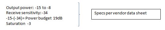
A laser transceiver has specifications based on its wavelength, which is documented in a number of values by the vendor, who actually manufactures and tests the fiber transceiver. The most notable values are Output Power, Receive Sensitivity, Maximum Input Power (Saturation), all of which are listed in dBm, decibel per meter. Spec sheets will also document the minimum and maximum wavelength for the transceiver, plus many other specs.
The Output Power is a range of power that a particular wavelength is capable of , for example, a SM 1550nm transceiver will often have an output power range of -2(min) to +3(max) dBm. On the other hand, a MM 850nm transceiver could have an output power of -10(min) to -4(max) dBm.
Receive Sensitivity is the minimum energy required for the fiber transceiver to detect an incoming signal, measured in dBm; it is usually a single value of anything from -23 to -36 dBm.
Saturation is the maximum power input allowed before overdriving the receiver; this value is typically -3 or 0.
Attenuation is the reduction of signal strength during data transmission. Attenuation per Km will occur on SM and MM naturally, and there are values based on EIA/TIA standards, for fiber core/wavelength. To keep things simple, just know that the SM 1310nm will generally be 0.35dB per Km, whereas MM 850nm will suffer 3.00dB per Km. Therefore, Attenuation is really only applicable to SM transceivers, and in particular, for an application going less distance than the transceiver is capable of.
Let’s get real
When a customer is spec’ing a fiber installation, or troubleshooting it after the fact, he usually wants the above values. He will use the common formula of Output power-Receive Sensitivity=the Power Budget. However, he will also want the Saturation value, to know that if he exceeds that value, his fiber device will need attenuation of some kind. Although fiber has some natural attenuation per Km, the distance being covered may demand more. Here is a good example.
The fiber segment between two end points is 1000’, or 0.3Km, and SM fiber has been pulled. The customer purchases a typical fiber network device that has a SM fiber interface which will cover up to 40Km.
The Saturation value is -3 and if that value is exceeded, then attenuation has to be introduced. If attenuation is not added, significant packet loss will occur. Since the 40Km fiber transceiver is going to only cover 0.3Km, attenuation is definitely necessary. There are three ways to arrive at this conclusion:
- Get a power meter and measure the line (expensive but accurate)
- Perform the complex calculation that has to include the above values plus losses on the line, including connectors, loss per Km based on fiber type and other factors. I’m not going to dive deep into the calculations, but the upshot is that the power budget of 19dB – the losses of 9.26 yields 9.74. Subtracting -8 maximum output power from the 9.74 gives you 17.74 dBm, and when comparing it to the -3 saturation value, you can see that you need to add attenuation.
- Realize that anything significantly less than the distance the transceiver supports is going to need attenuation, and add 10dB of attenuation ( a consistent rule of thumb) to reduce the signal strength and ensure that data will get seamlessly from point A to point B.
Fiber optics provides many benefits for network connectivity, but some of the specifications create a direct impact on the success and performance of it. One can determine how to avoid unnecessary downtime by referring to the fiber vendor’s specification sheets for Output Power, Receive Sensitivity and the Power Budget and doing a quick calculation.
Recommended Posts

Co-Creation, Paving the Way to a More Connected Future
November 27, 2018

The Benefits of a ‘Do It For Me’ Mentality in the IIoT
October 5, 2018

Why You Need to ‘Mind the Gap’ in Manufacturing Technology
August 31, 2018