RS-485 Connections FAQ
How Do I Make RS-485 Connections?
First check the pinout connections and specifications of the devices you want to connect in order to determine whether you need a “2-wire” RS-485 connection or a “4-wire” RS-485 connection. If you can’t obtain this information before selecting a converter or serial card, select a converter or device which can be easily set to work in either mode using switches, jumpers or other options. Most often you will be setting up and connecting a card or converter as a Master to one or more Slave devices. Following are figures for three types of 2-wire Master connections, and one type of 4-wire connection. Usually Termination is not required for baud rates 19.2K or lower at distances up to 4000 ft.(1220 m), so it is not shown in the simplified figures which follow. (see note on page 3 regarding markings and pinouts).
Figure 1 applies to many Ethernet/Serial Servers and a few B&B RS-485 Converters such as the 485SD9TB, 485SD9R, 485SD9RJ.
Figure 2 applies to several B&B Converter models such as the 485LDRC, 485LDRC9, and 4WSD9R. Two switches are set for 2W or to the 2-Wire RS-485 Mode.
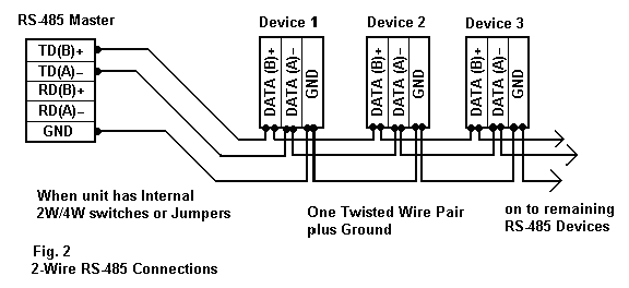
Figure 3 applies to most B&B RS-485 Converters or Serial Cards that can be set for 2-wire or 4-wire operation, and for some 2-wire Converters that use the same circuit board for the RS-422 model. Check the Data Sheet schematic or block diagram. Figure 3 is also used for Repeaters/Optical Isolated Repeaters such as the 485OP, 485OPDR. A RS-422 device does not tri-state the transmitter so it cannot use these connections.
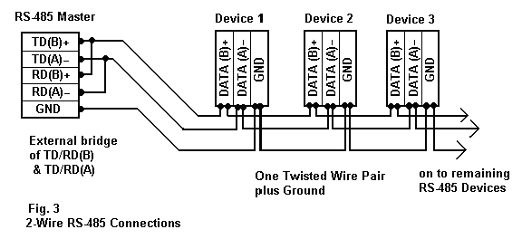
Some Converter models are: 485BAT3, 485COR, 485CON, 485COSR, 485COSN, 485CSP2, 485TBLED, 485LP9N, 485LP9, P485BTB1, 485HSPR.
4-Wire Connections
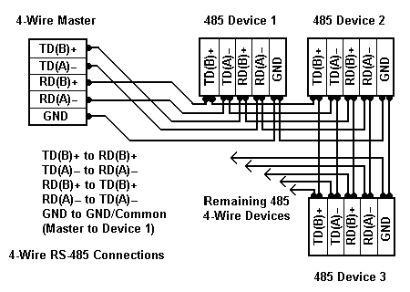
This connection is used for a single Master in a 4-wire system. When only one master is used, the Master can be set to RS-422 mode since the there is no need to share the transmit wire pair to the Receivers of all the devices. All of the devices must be RS-485 and Tri-state since the same wire pair to the Receiver must be shared by the Transmitters of all the devices. The advantage of the 4-wire connection is that all devices only see commands from the Master, and no Device sees the responses from other devices. Turn-around delay is also not required.
MULTI-MASTER CONNECTIONS
2-Wire Multi-Master
Connect additional Masters the same as any Device, (Figs. 1-3) matching the polarity of the A and B data lines. All devices must be able to ignore the commands to other devices and able to ignore the responses from other devices. Any device could transmit to all others if permitted or some special Protocol is established to avoid data collisions. Usually the devices are Slave type and respond only to requests from a Master Device.
4-Wire Multi-Master
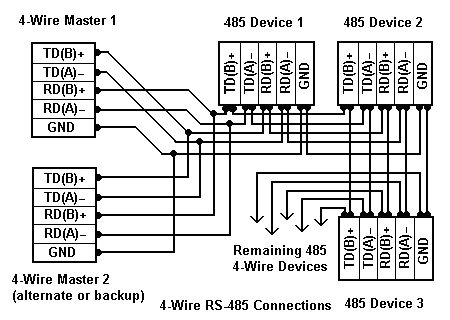
This connection is less common, Master 2 may be anywhere else on the network and may be used for collecting data returned from the devices. It can monitor the data from the devices only, but is not able to monitor the data requests from the other Master without additional connections. Only one Master can talk to the Devices at a time, so one Master must stop transmitting for a time (to avoid data collisions) so the other Master can access the same devices, or use some software protocol established for Device sharing. When Master 2 is used as Backup, the program on Master 2 begins polling the devices when the slave Devices stop responding for a predetermined time.
Note on RS-485 Pinout markings: Sometimes a device will be marked with the polarity reversed from normal RS-485 standards where the Data A or TD(A)/RD(A) line is (+) and the Data B line or TD(B)/RD(B) is (-). In a system with 2-wire connections, try reversing the lines to see if the device will respond. In a system with 4-wire connections, try reversing the receive pair polarity and transmit pair polarity. If the connections are wrong, you won’t be able to communicate because the data bits are upside down, but swapping polarity won’t damage anything. The marking Rx or Tx may be used instead of TD and RD or in a 2-wire system, TxRx+ and TxRx-, or Dx+ and Dx- for the Data lines. Many naming schemes are in use. RS-485 pinouts also have many variations, there is no single standard pinout arrangement or connector type, DB9, DB15, DB25, RJ-11, RJ-12, RJ-45 or DIN connector.
Recommended Posts

Technical Note: Why Network Security is Becoming More Important
August 16, 2018

eBook: Protecting Against Malicious Threats in Ethernet Networks
August 13, 2018
3 Questions to Ask Before Selecting an LTE WAN
June 15, 2018

